|
+ Basics:
In Loq Airou you model with one primitive: Creased Subdivision Surfaces.
The basic idea behind SDS(SubDivision Surfaces) is that the user creates
a cage of flat polygons and the software uses an algorithm to compute
a smooth third degree surface. This primitive has a number of advantages, first
of all it is simple to use, it creates great looking surfaces and it has
arbitrary topology. Since not all objects are smooth we have added the
ability to have creased edges making it possible to model sharp edges.
Loq Airou uses single sided surfaces, this means that surfaces
can only be visible form one side. The surface is also non-manifold,
which means that only 2 polygons can use the same edge. The
control mesh is restricted to only triangles and quads.
It is recommended to use mainly quads and to use triangles
in junction points between quads. This clears up the view and
makes it easier to see your model. Quad based models also tend
to be easier to make smooth.
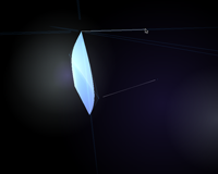
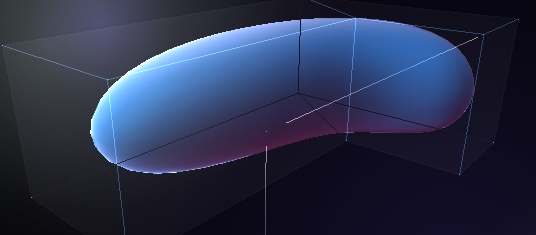
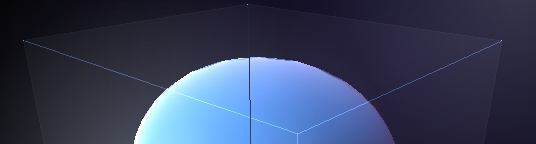
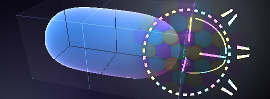
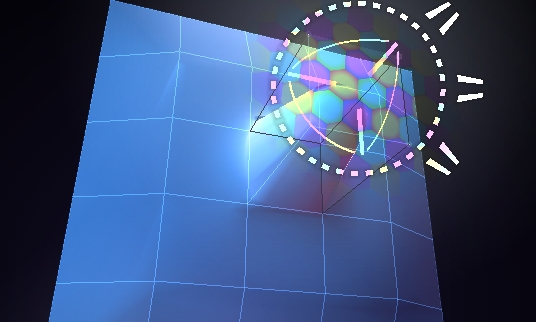
When viewing the model you actually can see two different
surfaces, first you have the actual surface (in blue) and then
you have the cage (transparent). The cage is the geometry that
is modified so when we refer to modifying the different parts
of model we always refer to the cage, and not the actual surface.
Sometimes some functions are applied to polygons and not to
vertexes. In these cases the application will consider them
selected only if all vertexes used by that polygon is at least
0.01 selected. Selected polygons appear slightly brighter so
they are easy to see. This unification of polygon and face select
removes the need to switch between two different modes when
modeling and allows the user to use the same tools for all types
of select.
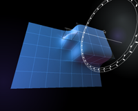
When a vertex is even 0.01 selected a manipulator appears.
A manipulator is a gizmo that gives you access to some basic
ways of manipulating the selection like Move, Rotate and Scale.
The full capabilities of the manipulator will be explained later.
Since Subdivision surface modeling is very much like polygon
modeling you can turn of the SDS surface and only display the
cage and then you have turned Loq Airou in to a Polygon modeler.
It has been designed to be a SDS modeler with very detailed
control so it may not be useful for high polygon counts but
should be perfect for low poly counts, like game arts.
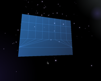
To modify already existing geometry we use selections. Selections
allow us to choose a specific part of an object and then apply
an action to it , like move it, rotate it, or scale it. The
selection is per vertex and can be considered a number between
zero and one, where zero is not selected and one is fully selected.
But you can also have a vertex with a selection value of 0.5.
This means that 50% is selected and that if possible actions
will only be applied 50% to this vertex. This is very useful
when you want to modify large parts of a model in a smooth way
and it gives you the ability to modify the model as it if were
clay.
+ Running The Software:
First you must start a verse server, do this by clicking on the
server icon and then start the modeler. In order to use the
modeler you must now connect to a verse server, if the server
you want to connect to is on the same machine as the modeler.
Click on the line to type in a host name or IP-Address if the
server is running on a remote machine.
Tip: Connect several modelers to the same server to be able
to collaborate on models. This can be done on a LAN or over
the Internet.
Now you enter the object browser, here you can see all the
objects on the server and you can choose one to model. If there
are no objects present press the "create Object" button at the
bottom of the screen.
You can also press Disconnect to
disconnect from the server or exit to quit the modeler.
Once you have Chosen or created a new object you can click on the object to enter
the modeling environment.
 + Changing The View:
By pressing the Right mouse button you can rotate around the
model, by pressing the left button while holding the right down
you can zoom in and out and by pressing the left button while
holding the right down you can pan. If you press Both left and
middle while holding down the right mouse button you can
reset the view. Right clicking on the manipulator focuses the
view around the manipulator.
+ Creating Geometry:
In Loq Airou you do not draw surfaces but rather edges that
create surfaces when connected. Any edges that forms a triangle
or quad will create a surface. When a polygon is created it
will be turned in the same direction as its neighboring polygons.
If there are no neighboring polygons it will be created facing
the camera. If the neighboring polygons are facing different
directions the modeler will create the polygon facing the direction
of the majority of the neighbors (or towards the camera if there
is tie). When a polygon is created it will delete neighboring
polygons facing the wrong direction or polygons that break the
two polygons per edge rule. This takes some time to get used
to but turns out to be fairly intuitive. It is recommended that
you as a user only use this creation tool to begin with until
you are comfortable using it.
By clicking and dragging with the left left mouse button you
can create an edge. Both ends can be snapped to existing geometry
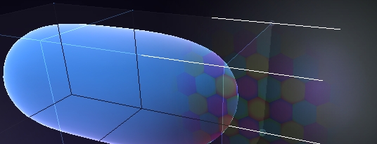
to make connected edges. The edges are by default created in
the view plane, perpendicular to your view point, the depth
is depending on the last drawn point. However when you draw you
can see three lines representing X, Y And Z and by drawing close
to them you can draw in a specific dimensions and not just in
the view plane.
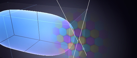
If you which to draw in a plane perpendicular or one of the
three axis (x/y, y/z or x/z) you can do by placing the camera
in roughly one of the 3 axis. The software will then snap the
drawing plane to the closest axis.
Note: at this time there is no indication to when the view is directed close
enough to axis for the snap to be active, this will be addressed in future versions.
To create a continuous line consisting of multiple edges you
can tap the middle mouse button while creating a edge to leave
off vertexes.
+ Snap:
In order to create geometry you some time need to match 2
edges distance, this is done whit the Right mouse button. While
creating an edge in one of the 3 axes and holding down the left
mouse button you press the right mouse button and move the mouse
over to the vertex you want to snap to then release the left
mouse button to create an edge.
If you press the right mouse button while drawing outside
one of the axes the software will choose the axis closest to
where you were drawing. This concept of right mouse button snapping
can be found in a number of places in the application like where
you are moving vertexes or using the transform manipulator.
Note: Releasing the Right mouse button will cancel the snap,
so be sure to release the left mouse button before the right
when creating the edge.
 + Delete Geometry:
To Delete edges or control polygons simply press the Left
mouse button in space and drag a line that crosses the edges
you want to delete. Make sure that the edge ends doesn't snap
to any existing vertexes. Delete only works on polygons facing
the camera and will not delete the surfaces turned away from
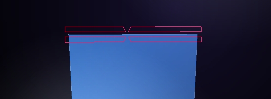
the view. When you are drawing an edge that deletes another
edge a red making appears on the edge. Make sure you see the
red marks when you want to delete and that you don't see them
when you want to draw an edge or do a selection.
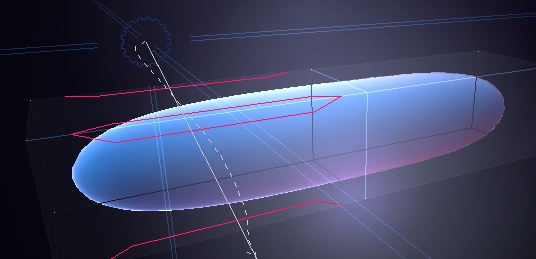
Notice the red overlay drawn over the edges you cross the edges.
They indicate that if the left mouse button is released the edges
and the surfaces will be deleted. Therefore you must be on the
look out for this symbol so that you don't delete geometry by
accident when drawing or selecting.
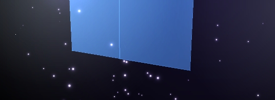
When an edge or surface is deleted
it turns to dust, this is a good indicator that a delete has been
made and gives the user a chance to undo the action if it was
not intended.
 + Creases:
To create a sharp crease, redraw an already existing edge,
if you redraw it again it will return to its smooth state. A
vertex connected to a sharp edge will be smooth. A vertex with
two sharp edges will create a sharp edge and a vertex with three
or more sharp edges will create a sharp corner. In general it
is wise to keep most edges smooth since it will be most flexible.
Even if you have a mesh where all edges are sharp, you may still
want to make the edges between two polygons in the same plane
smooth, since this makes it easier to change your mind.
note: that that the middle mouse button tap used to create
continuous edges also works to create continuous creases.
 + Select:
There are a number of ways to select and unselected geometry.
Three of them are available directly and the rest can be found
in the pop-up menus. Each of them has their own advantages so
it is recommended to use all of them.
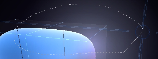
By left clicking in empty space and drawing a circle around
a part of a model, it will be selected. Be careful not to cross
any edges when releasing since this will trigger the delete
edge feature. If you when drawing a selection return to the
spot where you started your selection a pop-up will appear and
will give you a few options:
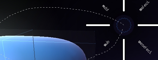
"Select" selects the circled vertexes.
"Deselect" selects the circled vertexes.
"Add" makes the selected vertexes 25% more selected then they are (but not more then 100%)
"Subtract" makes the selected vertexes 25% less selected then they are (but not less then 0%)
To deselect simply Left click in empty space without dragging. (dragging
will create an edge)
You can also select a vertex by simply clicking on it, be
careful not to drag it since that will create an edge.
You can also select all vertexes in a polygon by clicking on it. If some of the
vertices's already are selected the rest will be selected too, but
if all vertices's already are selected it will deselect all the
vertices used by the polygon. this allows you to toggle the selection.
+ The Manipulator:
The manipulator, can do many things and what it will do depends on where you
grab it. If you grab it in the middle you can snap the manipulators
position to a vertex with out modifying the selection, this
is useful especially since it makes it possible to decide the
axis of a rotation. It is also useful because the position of
the Manipulator is used for snapping.
By grabbing and dragging one of the 3 straight lines you can translate your selection in
the X, Y and Z axis. Pressing the right mouse button while dragging the selection
enables snapping, making it possible to snap vertexes.
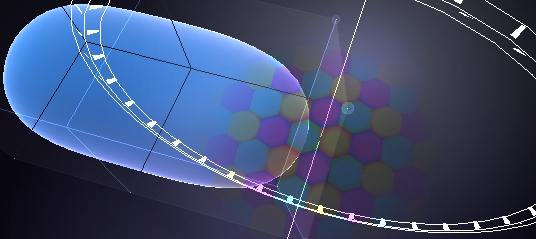
By Clicking inside one of the 3 arcs you can rotate the selection in one of the 3 axis.
When rotating a circle appears with markings for degrees and fractions. by moving the
mouse over them you can easily snap the rotation to a specific angle. You can also
use the right mouse button to snap to a vertex.
By clicking outside the arcs but still inside the outer circle
you activate the scale function. The scale is by default in
3 dimensions but by drawing along one of the three axises you
can limit it to one axis. Right Button snapping works here as
well, and it snaps to the outer edge of the selection. This
is very useful when you want to scale an selection to fit in
side a room.
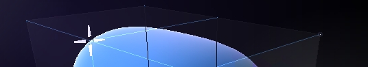
On the right side you of the manipulator you will find two
handles, they are used to move the normal and the tangent direction
of the surface.
The lower one moves the selections in the normal direction, this means in and
out. The normals are computed by averaging the surrounding polygons
normals for creating a correct normal. If a vertex is used by one
of more selected polygons its normal will not be influenced by
any polygons that are not selected.
The top handle is the tangent handle. It allows you to move
the outer edge of your selection in and out in the tangent plane.
Notice how all outer edges moves at the same distance. Tangent
and Normal Transform in conjunction with extrudes is a very
power full tool for solve a number of technical modeling problems.
 + The Extrude:
You can extrude selected polygons by middle clicking while you are transforming
a part of the geometry. (Selected polygons are polygons where all vertexes are selected.)
You can also press the middle mouse button multiple times to create multiple
extrudes. Extrude works with all forms of transform (transform, rotate, scale, normal
and tangent).
+ The Extrude:
You can extrude selected polygons by middle clicking while you are transforming
a part of the geometry. (Selected polygons are polygons where all vertexes are selected.)
You can also press the middle mouse button multiple times to create multiple
extrudes. Extrude works with all forms of transform (transform, rotate, scale, normal
and tangent).

 + Edge Split:
By left clicking on an edge between two unselected vertexes
you can split it. if the edge is used by a triangle it will
be split in two triangles, and if it is used by a quad it will
be split on to one triangle and one quad. Continuous splits
can be created by dragging over multiple edges.
To make sure that the start edge isn't selected so that the
reshape functionality isn't invoked, look for this overlay that
indicates that the edge will be split if clicked on.
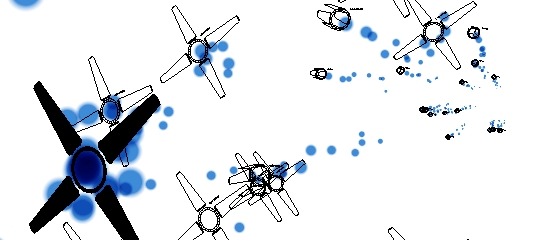
When splitting edges the edges will emit particles indicating that the split is in progress
some times you may want create multiple splits of an edge. to do this tap repeatedly on the
right mouse button wile you are splitting to increase the number of splits.
Once you have increased the number of splits you can press the middle mouse button to decrees the number of splits. Increasing and decreasing the number
of splits can be dome while you make a continues split to vary the number of splits in different areas of your model.
+ Moving individual Vertices:
Sometimes selecting and using a manipulation is not very practical
if you want to fine tune a model. Therefore you can just left
click and drag any selected vertex. This feature also works
with right button snapping. While dragging a single vertex you
can press the middle mouse button to collapse the vertex with
another vertex. This is useful for connecting 2 polygons or
to collapse an edge.
While you are dragging around the vertex you can tap on the middle mouse button
to increase the influence area and also move the vertexes around the one you are
dragging.
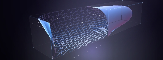
+ Hull Reshape:
This tool allows you to reshape a continuous line of edges and
is very useful for sculpting the shape of an object. Start by
left clicking on an edge between two selected vertexes. The
edge and edges connected will now be hi-lighted and you can
drag in the direction of the edge. When you pass the vertexes
in the junctions between the edges the vertices will move to
the position of the pointer. Tool works on both directions so
you can at any time switch direction, this gives you the oportunity
to re-draw an edge again and again untill the desired shape
is produced.
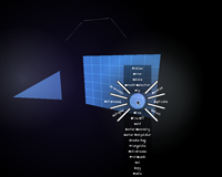
+ PopUp Menus:
In order to access actions pop-up menus are used. To access
the pop-up menus press and hold the middle mouse buttons. Different
menus appear depending on where you press the middle mouse button.
By pressing the middle mouse button in the void will bring up
a pop-up menu that gives you access to undo and redo but also
gives you the abbility to jump back to the browser to select
another object to edit.
The pop-up menus are directional based. To use them press
the middle mouse button and the menu appears, then move the
mouse in the direction of the action you want to access. Then
release the mouse button to activate the action. To cancel a
menu place the mouse pointer in the middle of the menu and release
the middle mouse button.
In a later part of this text we will go through all other
pop-up menus and explain that actions that can be found in them.
Popups are bought up by pressing the middle mouse button.
There are 5 diferent popups depending on waht you are point
at when pressing the middle mouse button. The different menus
found pressing the middle mouse button on:
The manipulator
An edge
A Polygon
A vertex
Nothing
The content of the pop-up relates to the type of menu, so applying
a change to the selection should be found in the Manipulator
pop-up. Some times the specific element the us used to bring
up the pop-up is used as an additional parameter for the action
preformed therfor we call this the "Action" Element.
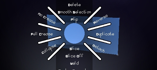
+ Manipulator PopUp:
The manipulator pop-up contains:
Reverse
Duplitcate
Detach
Collapse
Full crease
No crease
Flip
Smooth Selection
Delete
"Reverse", makes all non selected versexes selected and all
selected versexes unselected. (all soft selection goes threw
the formula: new_selection = 1 - old_selection) This functionality
is very useful because you can now un select portion by using
Inverse Select. Select some vertexes and the inverse the selection
again.
"Duplicate", duplicates all selected polygons and selects
the new surface. When using this action make shore you use the
manipulator to move the new surface away form its position before
clearing the selection, otherwise you will end up with two surfaces
in the same place that can make it hard to separate them.
"Detach", Detaches all selected polygons in to a separate
entity.
"Collapse", Collapses all vertexes in to one. That will delete
some polygons of reshape some quads in to triangles. if the
single vertex created by the collapse isn't used by any polygon
it will be deleted. A Detach folowed by a collapse can be used
to delete selected polygons.
"Full crease", makes all selected edges creased.
"No crease", makes all selected edges uncreased.
"Flip", turns all faces to face the opposite direction. all
non selected polygons that shares a edge with a selected polygon
will be destroyed since a single edge can not have two polygons
facing different directions.
"Smooth Selection", makes the vertexes selected borders semi
selected and expands the selection to make surrounding vertexes
some what selected too. This Action can be applyed multiple
times to get an even smoother selection. It is a very useful
function since it turns the transform manipulator in to a deformer
style tool.
"Delete", Deletes all selected polygons. it is a use full
alternative to the standard delete tool since it allows you to
select large pieces of geomety and delete them quickly.
+ Edge PopUp:
The edge pop-up contains:
Select border
Revolve
Tube
Select hull
Colapse
Measure
"Select border" selects all vertexes used in open edges (edges used by only one polygon)
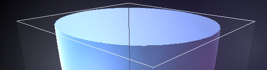
"Revolve" creates a revolve form the profile of 2 or more
edges not used by any polygons where one of them is the action
edge. The action will find the end of the continuous edges in
both directions and use them as the axis on the revolve.
"Tube" creates a sub shape that continues in both directions
of the action edge to find a continuous edge line.
"Select hull" selects the action edge and tryes to find further edges to create
a long array of selected edges in both directions of the action
edge. This tool is useful for editing revolves.
"Colapse" colapses the action edge
+ Face PopUp:
The face pop-up contains:
Mirror
Flatten
Fill selection
Deploy
"Mirror", mirrors the selected vertexes, using the action face as mirror plane.
"Flatten", moves all selected vertex into the plane of the
action face. The action tryes to preserve the planes of the
the surrounding faces making it possible to make multiple Flatten
actions on the same model.
"Fill selection", select all polygons some how connected to the action polygon
"Deploy", takes the polygons connected to the action polygons
and copies and pastes them "face against face" to all selected
polygons. For example if you create a landscape and select a
number of polygons on it. Then you create a tree and then use
the action deploy in the bottom of the tree, the action will
paste one copy of the tree on every selected polygon. Deply
works only if the Action face has the same number of edges as
the selected faces.
|